05 / 11Supporting / Industrial Reliability
BC-54 Idler Reliability Study
A finite-element and failure-mechanism study of catastrophic carrying-idler shell damage in the BC-54 coal-handling conveyor at PLN Indonesia Power Banten 1 Suralaya Unit 8.
01Context
The engineering problem
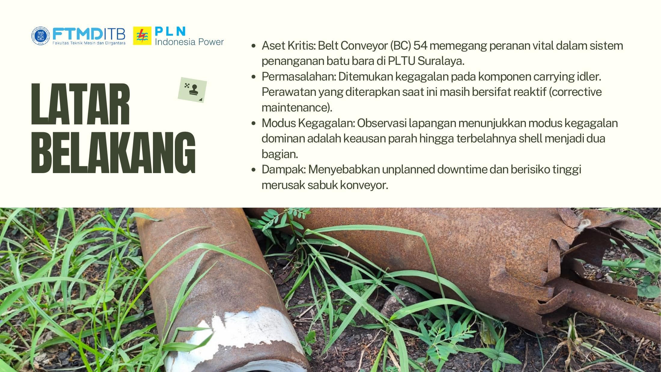
Field failures were severe enough to split an idler shell, yet maintenance was largely reactive. The study needed to determine whether the original design was structurally inadequate or whether another degradation mechanism explained the mismatch.
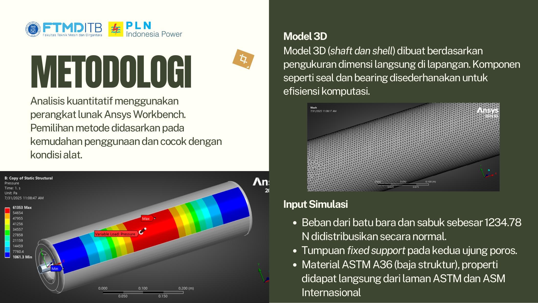
Measured the component in the field, translated the 800 TPH operating context into a 1,234.78 N equivalent load, built a simplified ASTM A36 shaft-and-shell model, and compared static and fatigue results with physical failure evidence.
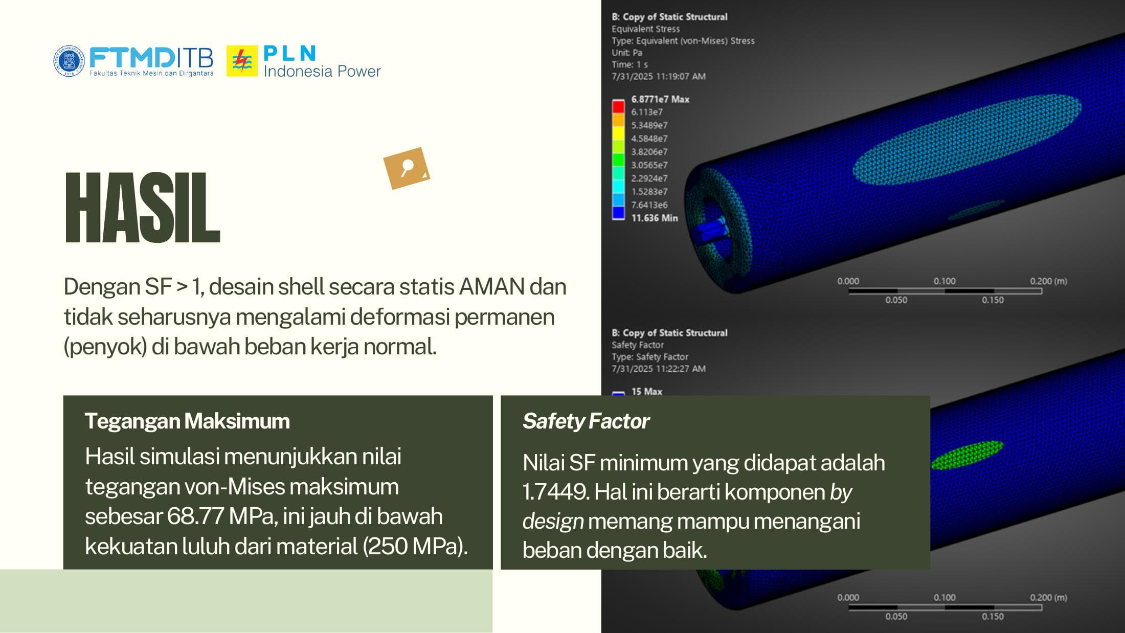
The model returned 68.77 MPa maximum von Mises stress, a 1.7449 minimum static safety factor, and a pure-fatigue prediction beyond one million cycles. That discrepancy redirected the root-cause hypothesis toward abrasive wear, wall thinning, and subsequent fatigue fracture, and informed a proposed ultrasonic thickness-inspection program.
02System architecture
How the layers connect
The diagram is paired with a text alternative and remains readable without animation or WebGL.
- Field evidence: Observed shell wear and catastrophic splitting on the BC-54 carrying idler.
- Load model: Converted conveyor capacity, belt mass, and idler spacing into a 1,234.78 N equivalent load.
- FEA: Evaluated static stress, safety factor, and fatigue life using a simplified ASTM A36 model.
- Reconciliation: Compared safe-model results with the failed physical component instead of stopping at the simulation output.
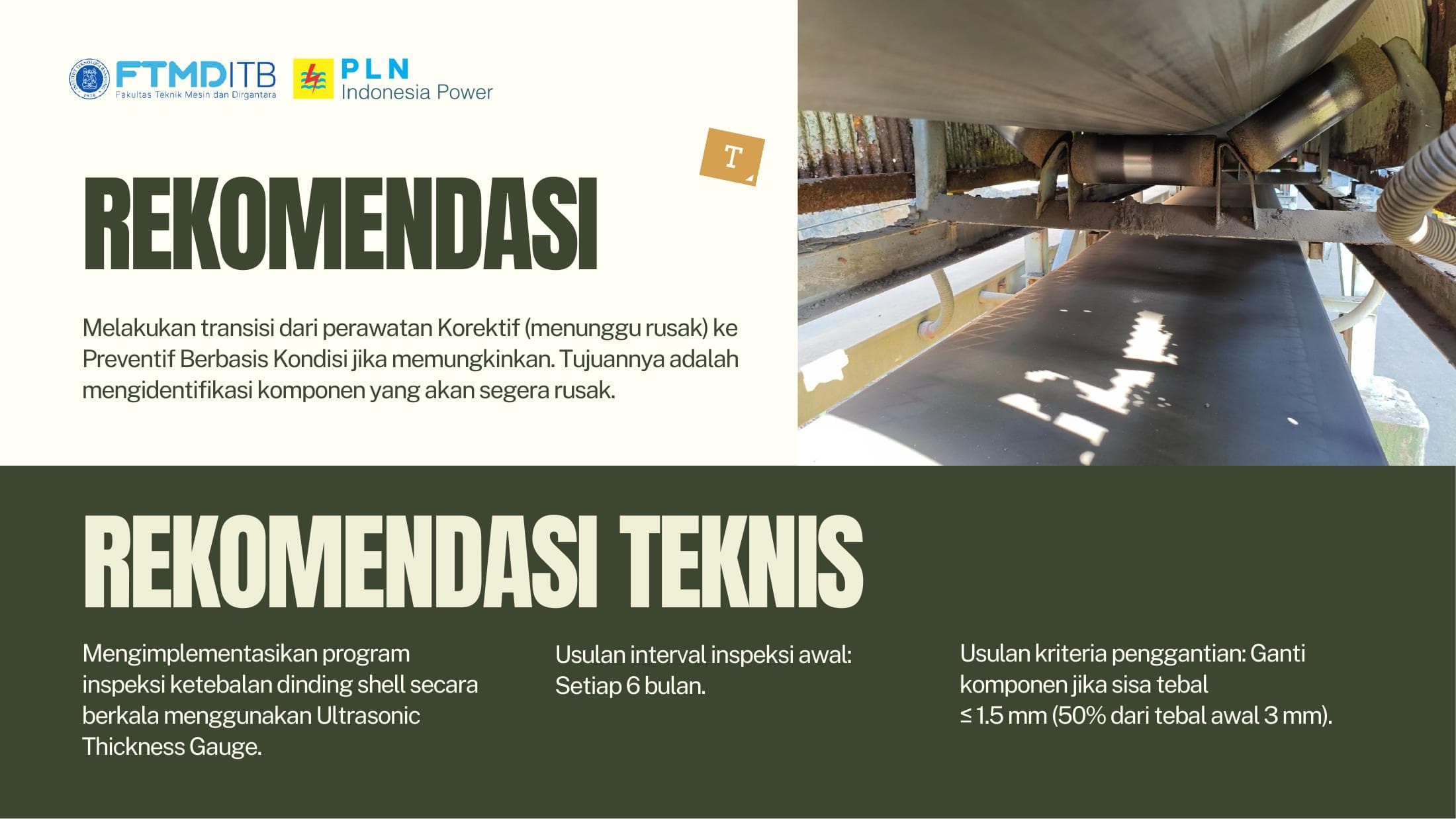
- Maintenance proposal: Proposed periodic ultrasonic wall-thickness inspection as a condition-based intervention.
03Engineering decisions
Choices that shaped the result
Treat disagreement as evidence
A safe static model did not invalidate the field failure. It narrowed the investigation toward degradation modes excluded from the simulation, especially abrasive wear and wall thinning.
State the model boundary
Bearings, seals, abrasive wear, corrosion, impact loading, and possible misalignment were not represented. The portfolio therefore presents the maintenance thresholds as analytical proposals, not verified plant outcomes.
Turn analysis into an actionable inspection concept
The report proposed an initial six-month ultrasonic inspection interval, a 2.0 mm warning level, and planned replacement at or below 1.5 mm, subject to refinement with real wear-rate data.
04Product evidence
Selected interface views
Captured from the deployed product. Authenticated screens are shown only in privacy-safe states.
05Technical footprint
Stack in context
- Ansys Workbench
- Finite Element Analysis
- Failure Analysis
- Field Measurement
- Condition-Based Maintenance
- 68.77 MPa maximum stress
- 1.7449 minimum safety factor
- >1M-cycle pure-fatigue prediction